


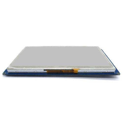
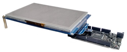
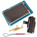
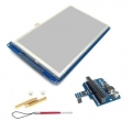
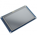
7" TFT 800*480 With SD Touch Module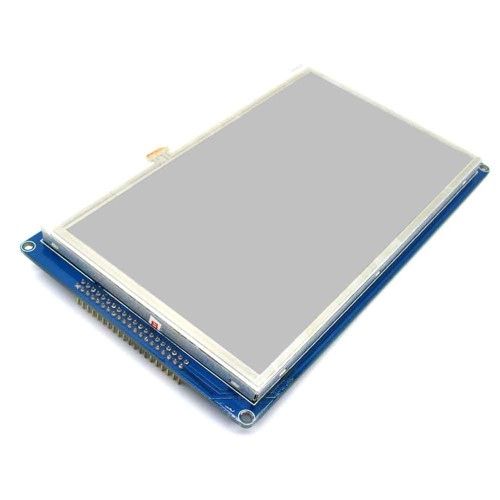
Description
Applicable CPU:51, Arduino, AVR, STM32, PIC, MSP430, DSP, ARM, etc.
TFT 7" 800*480 With SD Touch Module adopts 8080 timing sequence with 16-bit parallel bus interface, resolution of 800 × 480, display panel with 16M color and integrated with 8-page video memory (the remaining memory could be used as extended memory). The interior of module utilizes CPLD + SDRAM mode to drive RGB interface display, which does not only realize conversion between the bus interface and RGB interface, but also provides a range of useful features. For details, please refer to the following register descriptions and Demo program.
TFT 7" 800*480 With SD Touch Module adopts XPT2046 as touch screen controler.The XPT2046 is a 4-wire resistive touch screen controller that incorporates a 12-bit 125 kHz sampling SAR type A/D converter.
With regard to stability, the module is equipped with great anti-interference capability, which is far more powerful than the drive solution SSD1963 on the market, as anti-interference ability of SSD1963 is poor with risk of crashing and white screen.
As to functions, the module provides 8-page video memory which can achieve data writing on the background, a command is enough to switch to full-screen display of data instantly, which is far more functional than drive solution RA8875on the market.
Concerning control, as TFT 7" 800*480 With SD Touch Module does not need to be initialized, and a resetting operation is enough to make it work, thus those boring initialization codes which general TFT controllers require can be saved. A minimum of five register commands will be enough to make it operate normally, which greatly simplifies the codes and reduces the difficulty of debugging and probability of error.
The control board responds very fast, which can achieve reading and writing cycle up to 200ns and the highest full-screen refreshing speed of 13 frames. The integrated 8MB SDRAM corresponds to 8-page display buffer. The display page register and reading and writing page register are set up independently, and the current display page and reading and writing page can be different pages to facilitate the achievement of full-page fast switching after being written on the background.
TFT drive timing sequence and circuit design have been optimized to ensure accurate color recovery, stable display, to eliminate flickering or cross colors, and to provide LED backlight drive thus brightness can be regulated from 0 (closed) to 16 (full).
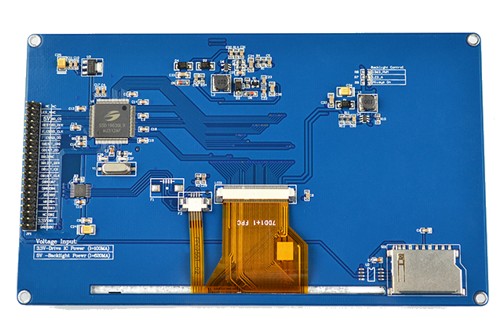
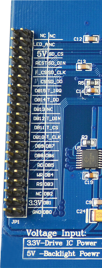
Note: SD_ prefixed pins are for SPI interfaces for multiplexing between SD card socket and FLASH, and they can be disconnected if they are not in use. F_CS is for flash potential energy (flash chip is reserved and the factory default is not to be soldered). T_ prefixed pins are for the touch interfaces, and they can be disconnected if they are not in use.
Work register configuration description
1) Backlight Control
Backlight is driven by 300Hz PWM signals with high energy conversion efficiency and no flicker. When the backlight register is set to 0, the backlight turns off. When the backlight register is powered up, the reset value is 0. To avoid blurred screen when powering up, you can clear the screen first when powering up, and then turn on the backlight. The maximum backlight value is 16 (0x10). When the writing value is greater than 16, it will be ignored.
2) Writing of row and column addresses
The corresponding RAM address of row and column addresses is obtained by internal arithmetic of the control board, thus users do not need to calculate the correspondence between the row and column addresses and the RAM address, and they can directly enter coordinates addresses.
3) Row and column address increment direction
Row and column address increment direction can be achieved by configuring "address increment direction register (0x0D)". The address is automatically incremented by 1 when writing continuously. The control board can be set as the row direction or the column direction address auto increment. When it comes to the end of the row, it will circulate to the beginning of the row.
4) Reading and writing data channel
When reading and writing display data, make sure that the work register value is set to 0x0F and selection points to data channel; when reading and writing display data, work register cannot be modified to other values, writing will be failed.
5) Resetting and initialization
After the drive board is powered up, RST pin will control resetting. Resetting of low level needs to keep for 1ms to ensure reliable resetting, internal initialization of module can only be done when the resetting pin is pulled to high level and lasts for 1ms, and then data can be written.
This TFT can be used with 7" TFT Shield for Arduino Due
Working voltage: 3.3V
Default IO connections :
Control Line:RS-P3^5; WR-P3^6; RD-P3^7; CS-P1^0; REST-P1^2;
Data Line: DB0-DB7 connect with P0^0-P0^7; DB8-DB15 connect with P2^0-P2^7;
Touch function of the connection :
(if you don't use the touch function and then don't connect)
D_CLK-P1^7; D_CS-P1^4; D_DIN-P3^0; D_OUT-P3^1; D_PENIRQ-P3^4;
●TFT Power: the power of the screen is 2.8-3.3V; don't use 5V, all pin voltage of this module must not exceed 3.3V.
●Backlight: the module has inherited the backlight driver circuit, When the LED_A interface connect with high level, then the backlight will be light; When the LED_A interface connect with low level, then the backlight will be not light; When the LED_A interface connect with PWM signal, then can control the brightness of the backlight.
●Special Note: the 4.3-inch and larger TFT backlight current consumption is relatively large, (the brightest 4.3-inch is more than 200 ma, the brightest 5-inch is more than 300 ma, the brightest 7 inch is more than the 600ma) If you are using USB power, then may exist some computer motherboards current supply is not enough, and it may cause severe partial pressure, which may causes the module does not work due to poor quality USB connection. Please make sure your power supply is stable enough.
Click to Download The Corresponding TFT 7" Zip Document
The Document Zip include as below :
* Lib_UTFT.zip Library of The TFT
* XPT2046.pdf Touch controller datasheet
* SSD1963.pdf Screen controller datasheet
* Spe.pdf Spe of the TFT
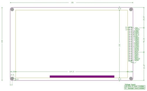
* Size.pdf Size of the TFT
* Schematic Diagram.pdf Schematic Diagram.pdf
* 51_test_program_keil_project.zip 51_test_program_keil_project
* Notice.pdf Notice
* Interface Port.jpg Interface Port Defination
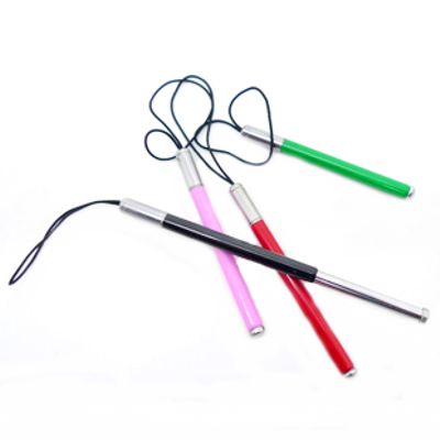
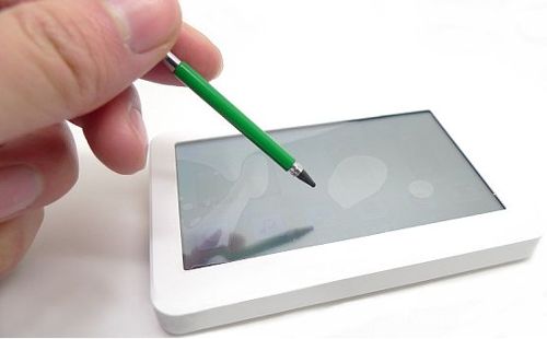
We will send free gift together with this TFT: Universal resistive touch pen
Related Items
-
 US$5.98
 -
 US$19.98
Join our newsletter today, to get latest product information and promotion code.
 |
 |
|

|